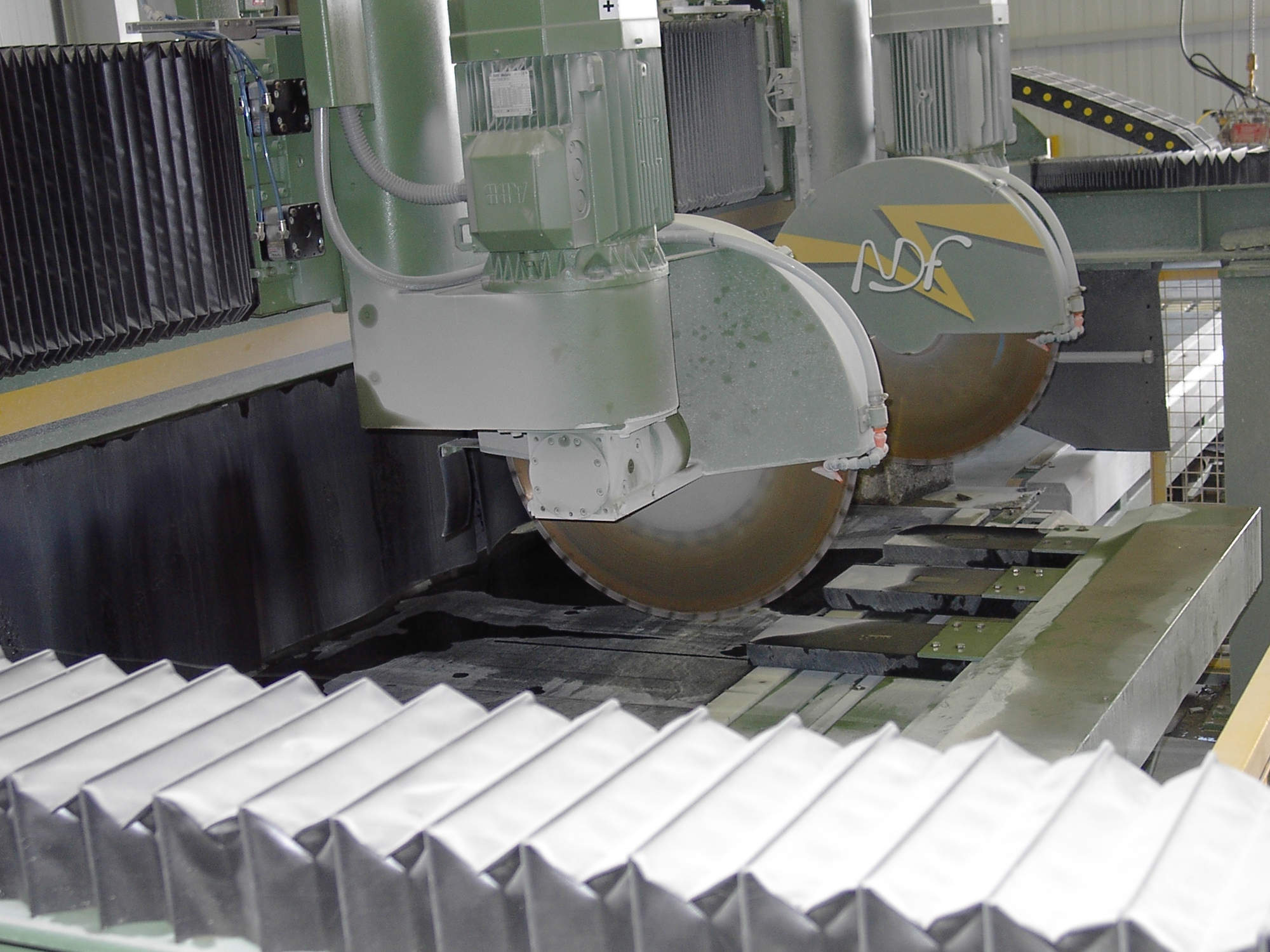
Cutting lines N2990/2200 2 + 2 heads
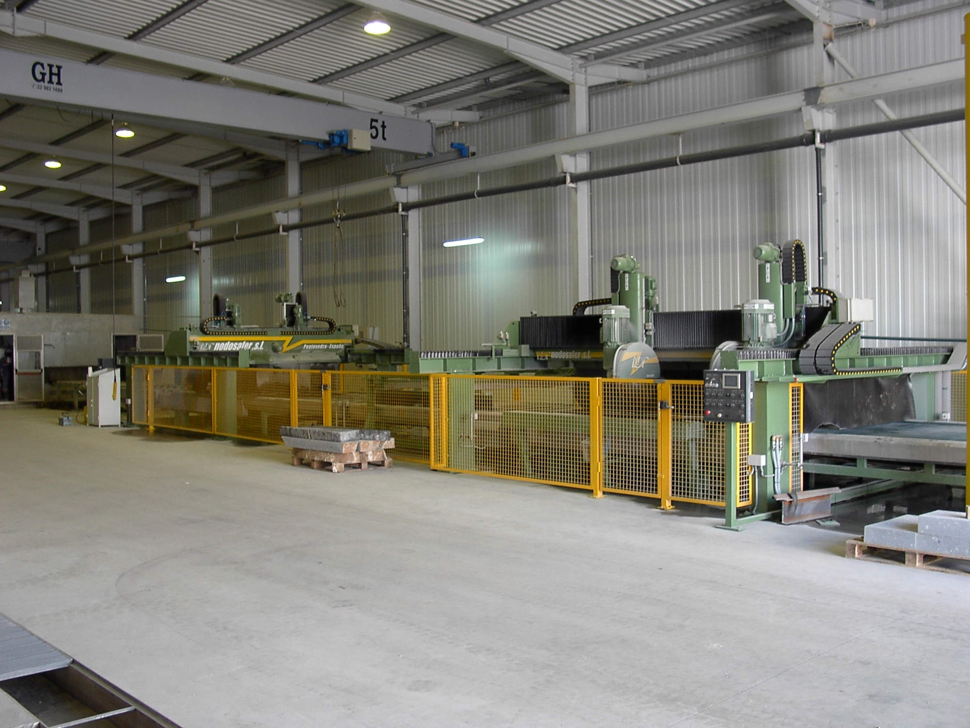
Cutting lines N2990/2200 2 + 2 heads specification
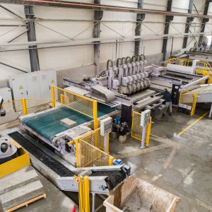
Our N.2990/2200 2+2 C cutting line has been designed to obtain maximum production with minimum operator work and maximum reliability of the machines that compose it. This cutting line includes:
- 1 Motorized plastic roller table N.2274
- 1 Longitudinal cutter Model N.8500/800-2C.
- 1 Cross cutter Model N.8500/800-2C.
- 2 Motorized Belt Tables Model N.2304.
- 1 Double displacement table with trailed motorized rollers and motorized rollers N.2585.
- 1 Table with stop selection of slice N.2590.
- 2 Belt motor tables for material output Model N2426.
- Security fence.
Cutting lines N2990/2200 2 + 2 heads documentation
Cutting lines N2990/2200 2 + 2 heads technical sheet
Our N.2990/2200 2+2 C cutting line has been designed to obtain maximum production with minimum operator work and maximum reliability of the machines that compose it.
DESIGN SPECIAL FOR THICKNESS
The general dimensions of the production line have been adjusted to the needs of the customer, in accordance with the criteria established by the same, in terms of the dimensions of the parts to be manufactured and the finished products obtained.
The entire line is characterized by the sturdiness and reliability of the machines that make it up, all designed to withstand the toughest working conditions. It is precisely in this regard that we can contribute all the experience accumulated over the years in the design and construction of machinery for the sector.
One of the great advantages that we can highlight of the machines of this production line is that they are models whose designs have already been evaluated in their operation and which only differ from our standard machines in their fundamental dimensions, but not by all the components that integrate.
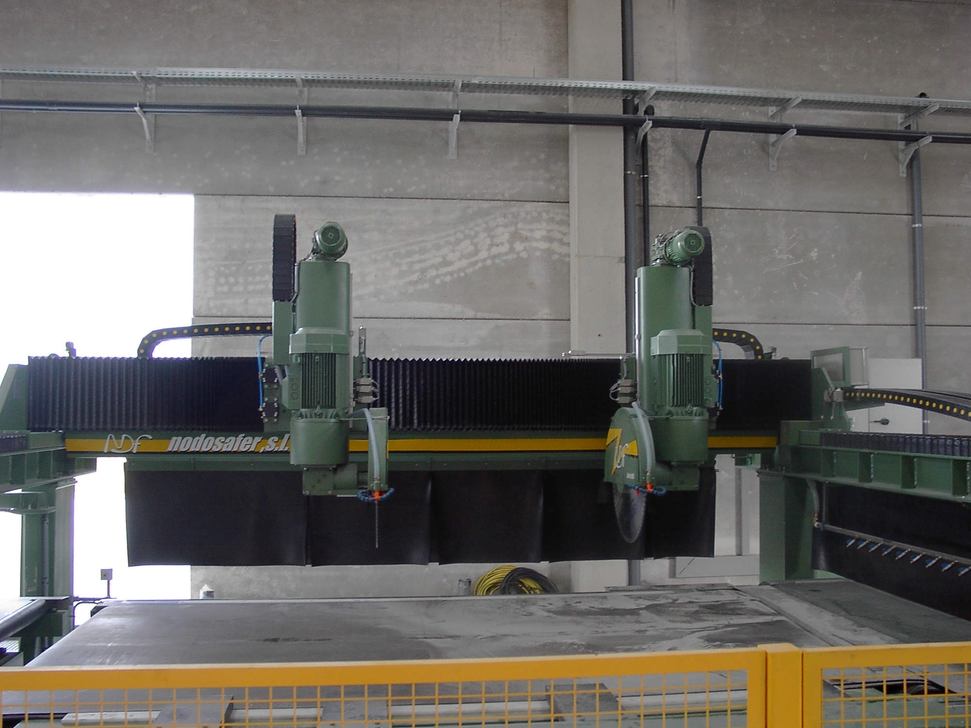
The longitudinal slitter with 2 heads on mobile bridge N.8500-2C and the transverse slitter with 2 heads N.8500-2C are machines equipped with the latest technological advances in mechanical and electronic design. Of particular note are the linear guide systems of the head bridge supported by two beams parallel to the cutting table per the first and perpendicular to the second, with precision linear guides and ball bearings and high precision and high rigidity recirculating shoe, which moves, to perform the cutting tasks.
The sliding disc-carrying heads resting on linear guides on the bridge, with recirculating ball pads, also perform the vertical movement guided on recirculating ball pads and driven by a laminated axis with a recirculating ball nut, in order to be able to position themselves very quickly and precisely, leaving everything perfectly protected by a PVC bellows. Head carriers equipped with a translation movement by displacement gear motor controlled by frequency converter and magnetic positioning rule on the X axis, and actuated by a spindle and an electric gear motor for the vertical positioning of the cut on the axis Z. The positioning of the heads is simultaneously thanks to the independent converters of each head.
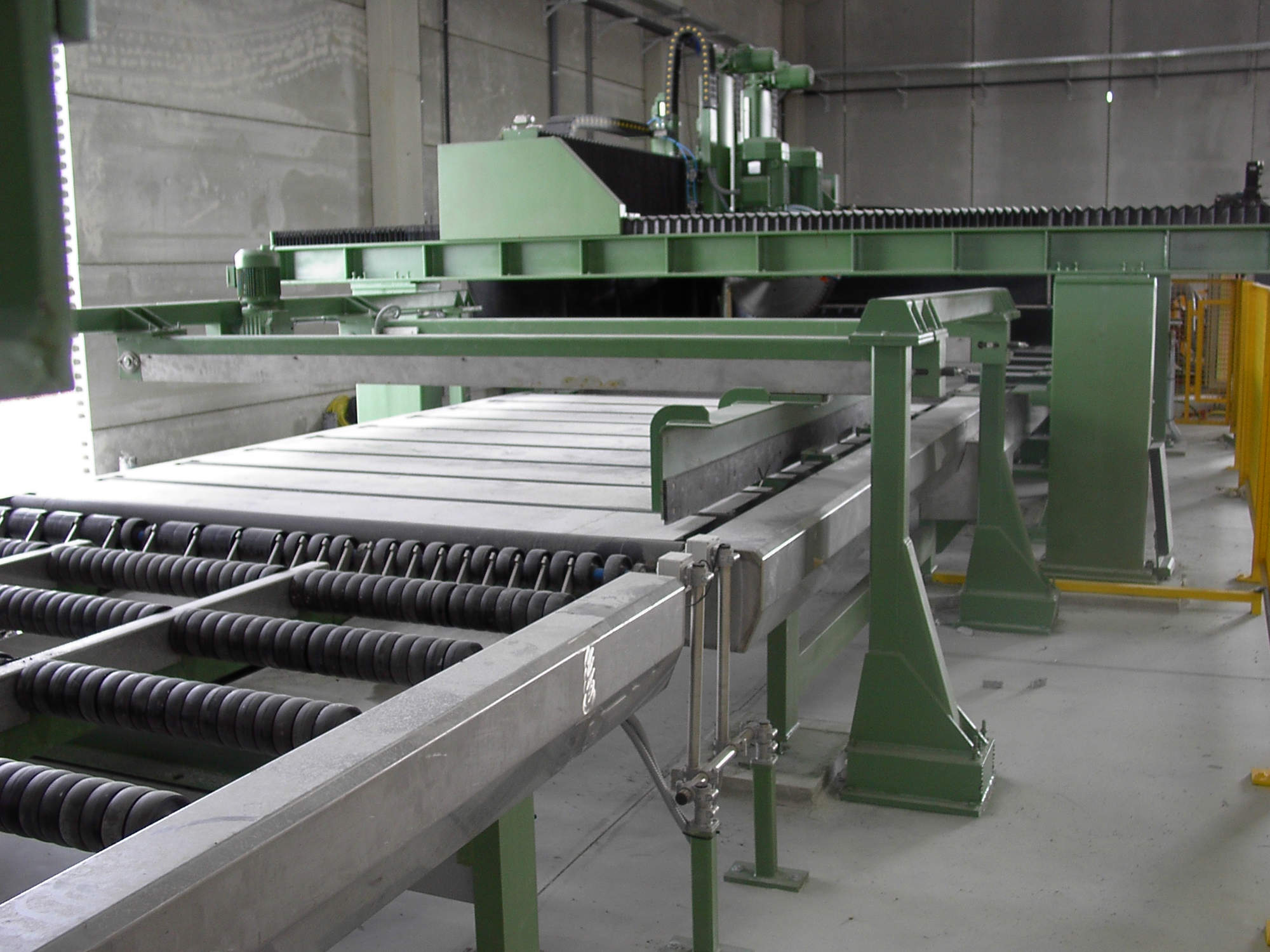
The N.2304 cutting tables are built with a steel structure with a rectified upper plane, on which the motorized conveyor belt rests, the outer surface of which is covered with rubber to prevent the movement of the material during the cutting phase. A stone striking device, located on the table of the second cross cutter, allows cutting times to be reduced considerably.
Table N.2590, located at the outlet of the longitudinal knife, has a system of pneumatically controlled physical stops that allows the selection of pre-cut strips according to width for subsequent processing in the longitudinal knife.
The second table N.2585, has a drag device to join and align the strips before processing in the cross knife, as well as the elimination of longitudinal waste.
The belt unloading tables N.2426 have a frame built on a steel grid with a conveyor belt to unload the cutting table, simultaneously, while the cross knife already receives the next board and is ready to cut.
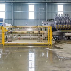
The work areas are protected, limiting access to risk areas by protective fences and photoelectric cells, in order to avoid any risk of accident.
All machines and heads are equipped with a centralized gear drive system for quick and easy maintenance.
In the section on electrical installation and control, it is worth highlighting the implementation of state-of-the-art automatons with programs tailor-made by our technical department, so that the programming of the machines is as simple as possible for the operators. , thus avoiding unnecessary waste of time. The programming of the working cycle and the visualization of its sequence are carried out on two operator terminals with a display, where all the working parameters are displayed, as well as the cutting cycles.
| Machine width | 5500 mm |
| Rolling ways length | 5500 mm |
| Maximum disks distance | 2200 mm (interior) |
| Minimum disks distance | 200 mm |
| Cutting disks diameter | 800 mm |
| Maximum height of the cutting pieces | 300 mm |
| Disk engine power | 30 HP (2) |
| Total power installed | 67.5 HP |
| Water consumption per disk | 30-40 l/min |
| Machine width | 5950 mm |
| Rolling ways length | 5500 mm |
| Maximum disks distance | 3500 mm (interior) |
| Minimum disks distance | 200 mm |
| Cutting disks diameter | 800 mm |
| Maximum height of the cutting pieces | 300 mm |
| Disk engine power | 30 HP (2) |
| Total power installed | 67.5 HP |
| Water consumption per disk | 30-40 l/min |
| Table width | 2957 mm |
| Max. Table length | 4044 mm |
| Max. Band width | 2200 mm |
| Band displacement speed | 6.5 m/min |
| Band displacement speed | 4.5 HP |
| Table width | 2929 mm |
| Max. Table length | 3700 mm |
| Max. working width | 2200 mm |
| Rollers forward speed | 6.5 m/min |
| Roller drive engine power | 1.5 HP |
| Centring displacement speed | 3.1 m/min |
| Transversal displacement engine power | 2 HP |
| Table width | 2929 mm |
| Max. Table length | 3500 mm |
| Max. working width | 2200 mm |
| Forward speed | 6.5 m/min |
| Drive engine power | 1 HP |
| Table width | 2929 mm |
| Max. Table length | 3900 mm |
| Max. working width | 2200 mm |
| Rollers forward speed | 6.5 m/min |
| Roller drive engine power | 1.5 HP |
| Table width | 2930 mm |
| Max. Table length | 3500 mm |
| Max. working width | 2200 mm |
| Rollers forward speed | 11.5 m/min |
| Roller drive engine power | 2 HP |


