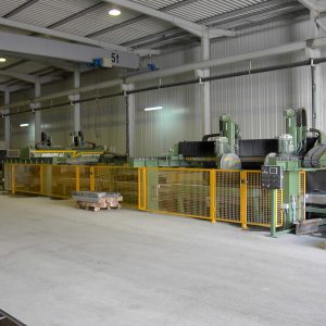
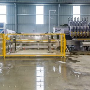
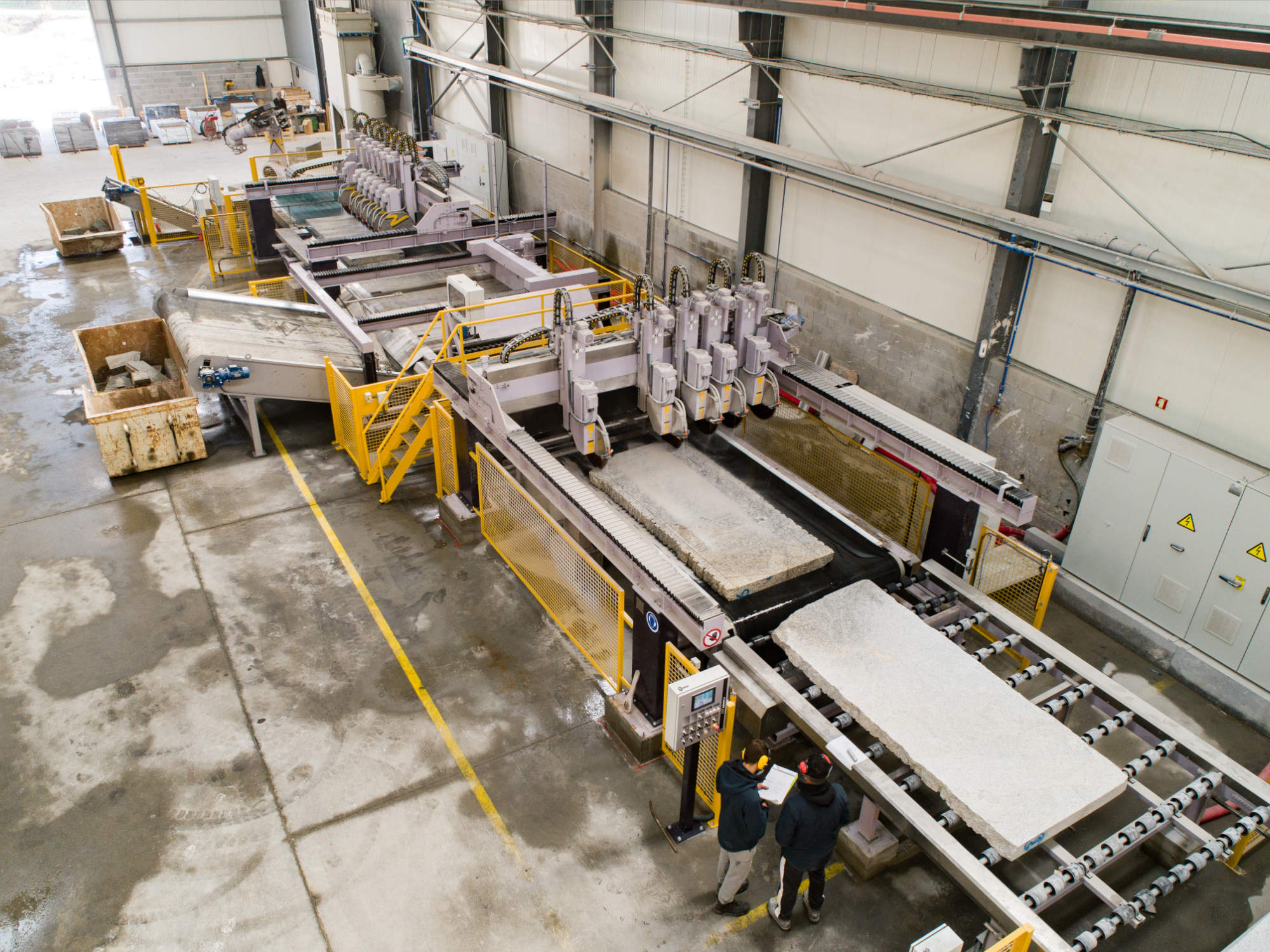
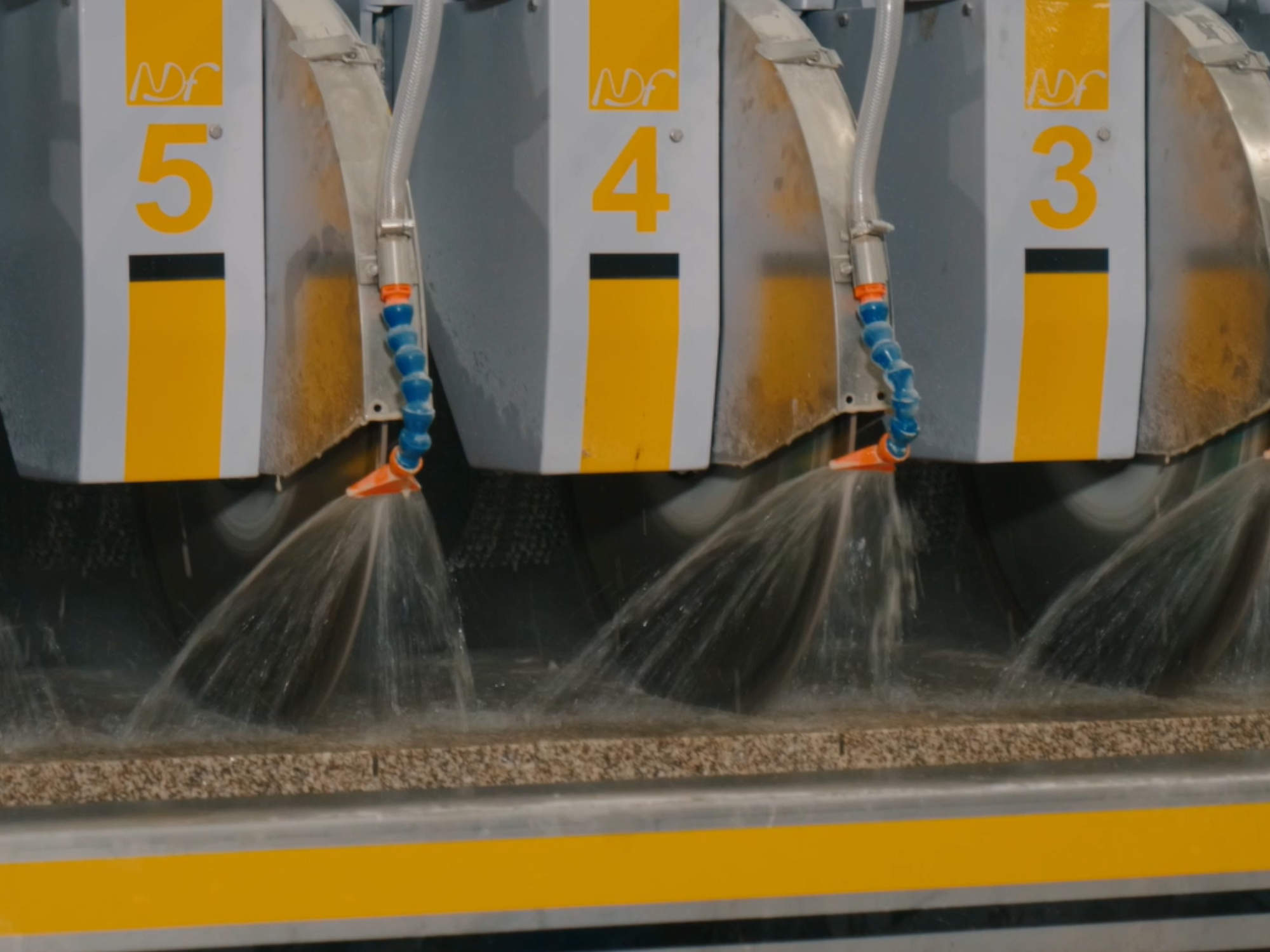
Cutting lines N2990/2200 6 + 9 heads
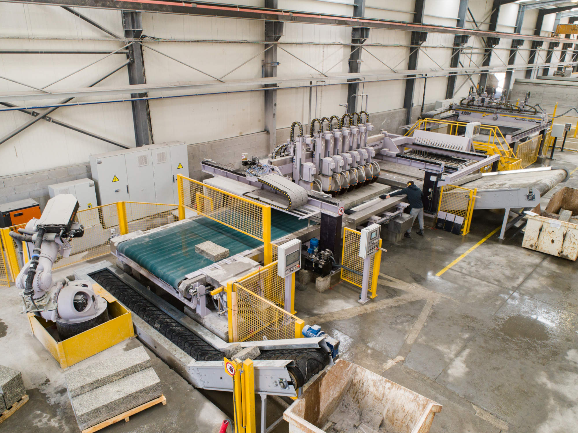
Cutting lines N2990/2200 6 + 9 heads specification
The N.2990/2200-6+9C cutting line parts are:
- 1 Intermediate motorized roller table , model N.2274
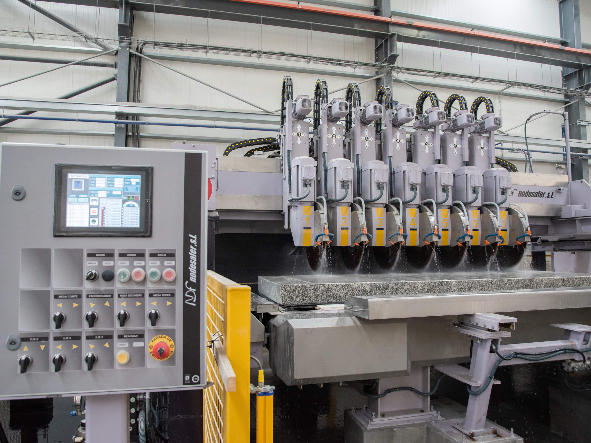
- 1 Longitudinal bridge disc cutter with six cutting heads for Ø600, model N.8000-L-6C
- 1 Transverse bridge disc cutter with nine cutting heads for Ø600, model N.8000-T-9C
- 2 motorized cutting tables with band, model N.2304
- 1 selection table, model N.2590
- 1 double displacement motorized roller table, model N.2585
- 1 motorized band table for product output, model N.2426
Cutting lines N2990/2200 6 + 9 heads documentation
Cutting lines N2990/2200 6 + 9 heads technical sheet
Our N.2990/2200-6+9C cutting line has been designed aiming maximum production capacity with lesser man labour needs, as so as with the maximum reliability of all its parts.
The production line overall dimensions have been adjusted to the customer needs, following his criteria about the produced pieces dimensions and the final products obtained.
The full line features better robustness and reliability in all its subassemblies, being them all designed to support the hardest working conditions. This is one of the most relevant aspects where our long time experience in manufacturing stone processing machines for this sector.
One of the great advantages of the machines integrating this production line is that all the designs are already tested solutions. They only differ from out standard machines in their overall dimension, but not on detail solutions or specific components.
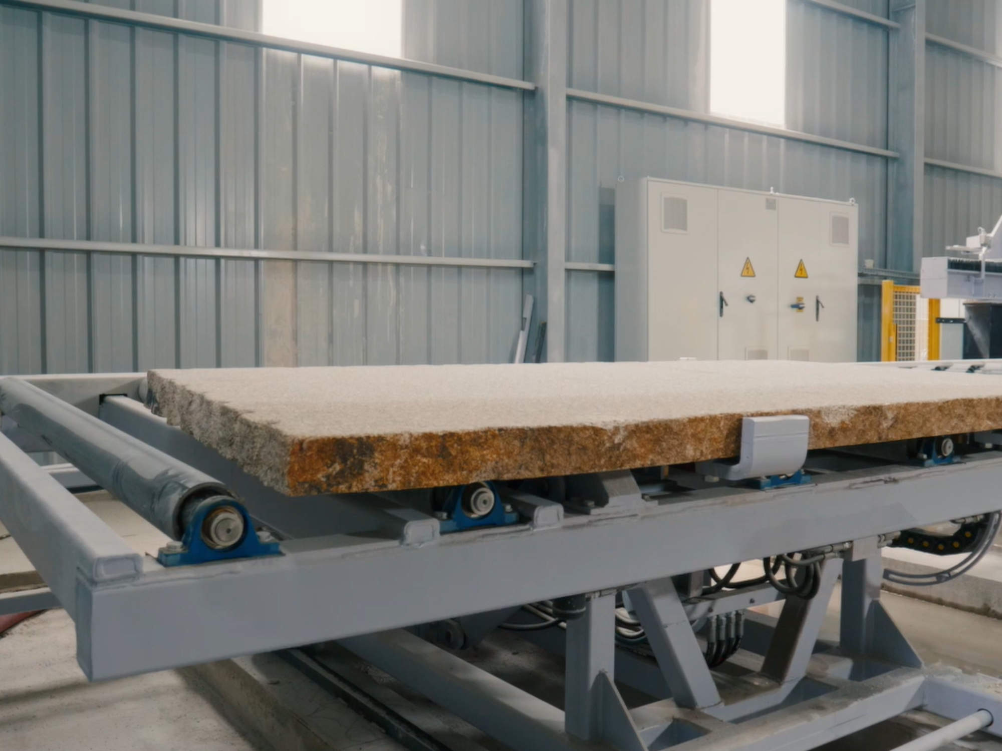
With the automatic loading trolley NDF-1289-P/V (optional) the longitudinal cutter is fed with material from a slab store. The slabs are taken via sucking cups connected to a vacuum pump and horizontally positioned onto a input roller table, ready to be fed to the line, in such way that they all share an alignment position, and it´s not necessary fit the point of beginning of the cutting machine
This table not only acts as the physical joint between the feeding trolley and the longitudinal cutter, but also serves as intermediate store, allowing to minimize lost times.
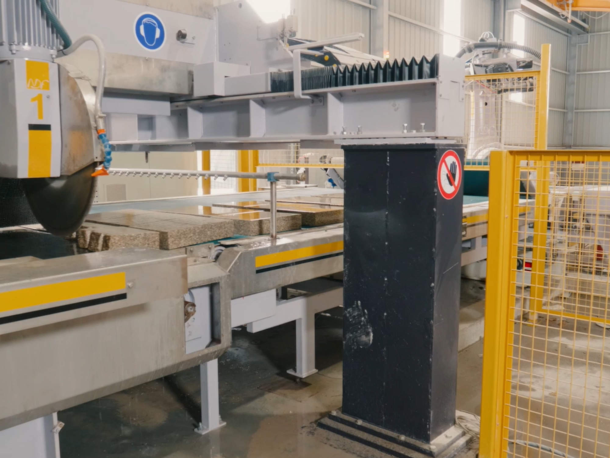
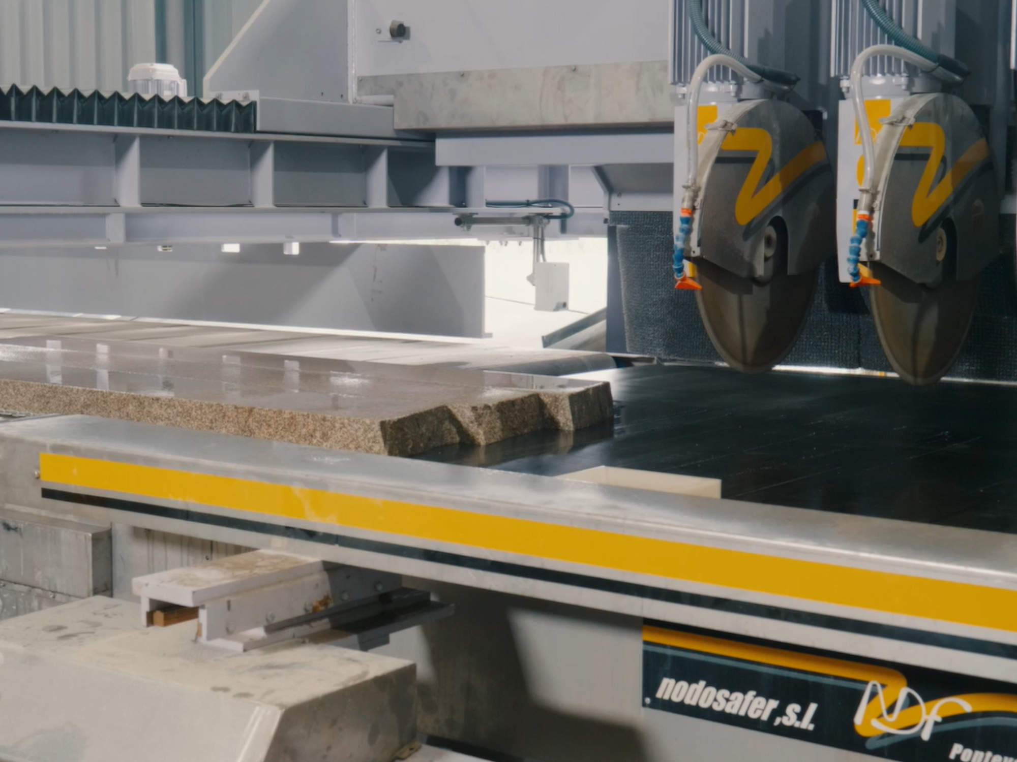
The 6 heads longitudinal cutter N.8000-L-6C and the 9 heads transverse cutter N.8000-T-9C are state-of-the-art machine, both in their mechanical design and in their electronics. These bridge cutters implements linear guiding in all their movements. The bridge is supported by two sliding heads resting over steel beams, being parallel to the cutting table the first, and orthogonal, the second.
The cutting heads use also ball runners in their translation along the bride and vertically perpendicular to it. This leads to a very smooth, quick and precise positioning. The position is inverter driven and implements a very accurate magnetic/optical measuring system. Vertical and horizontal movements are controlled by individual inverters so simultaneous positioning in both axes is possible. Every guide is conveniently protected by flexible PVC covers in order to avoid the dust damaging the mechanisms.
The N.2304 cutting tables consist of a steel structure with a machined top plane where the motorized transport band lies and slips. The band is rubber covered to avoid slab slipping during the cut process. The second cutting table under the transverse cutter adds blocking device to both lock the stone position and ensure the cut orthogonality.
Between the two bridge cutters are two special roller tables.
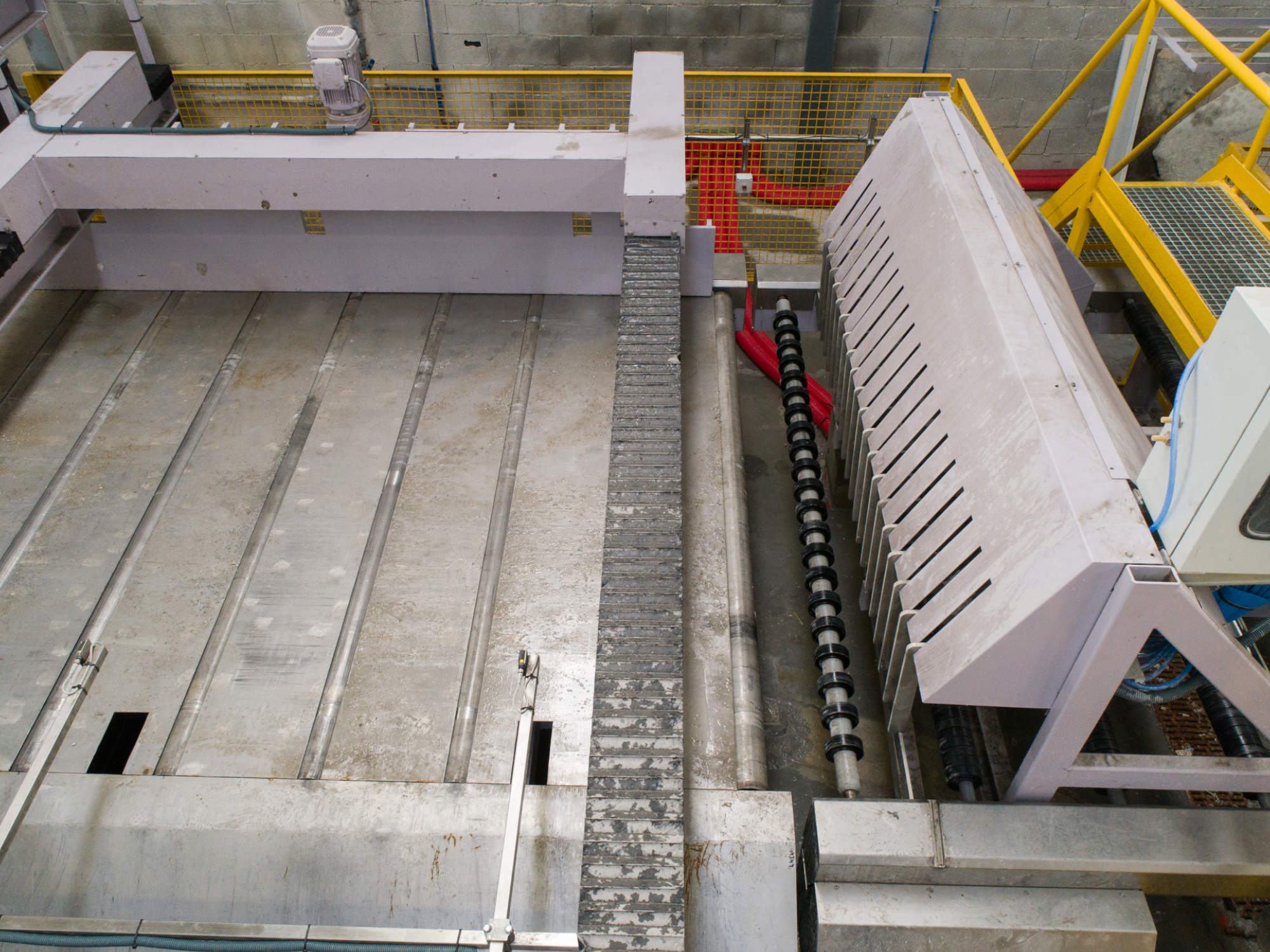
Just after the longitudinal cutter is the blocking roller table N.2590 that implements a set of mechanical blockers that, pneumatically driven, allow only the proper combination of stone bands to pass to the next step in each cycle.
The second table, the roller discarding table N.2585 implements a mechanical push and pull device with double function: joining the current processed stone bands altogether and throw the rubbish originated in the longitudinal cut away from the cutting line.
At the output side of the transverse bridge cutter the N.2426 unloading table is located. This one consist of a steel profiles frame with a rubber transport band, allowing the simultaneous loading and unloading of the last bridge cutter without any loose of time.
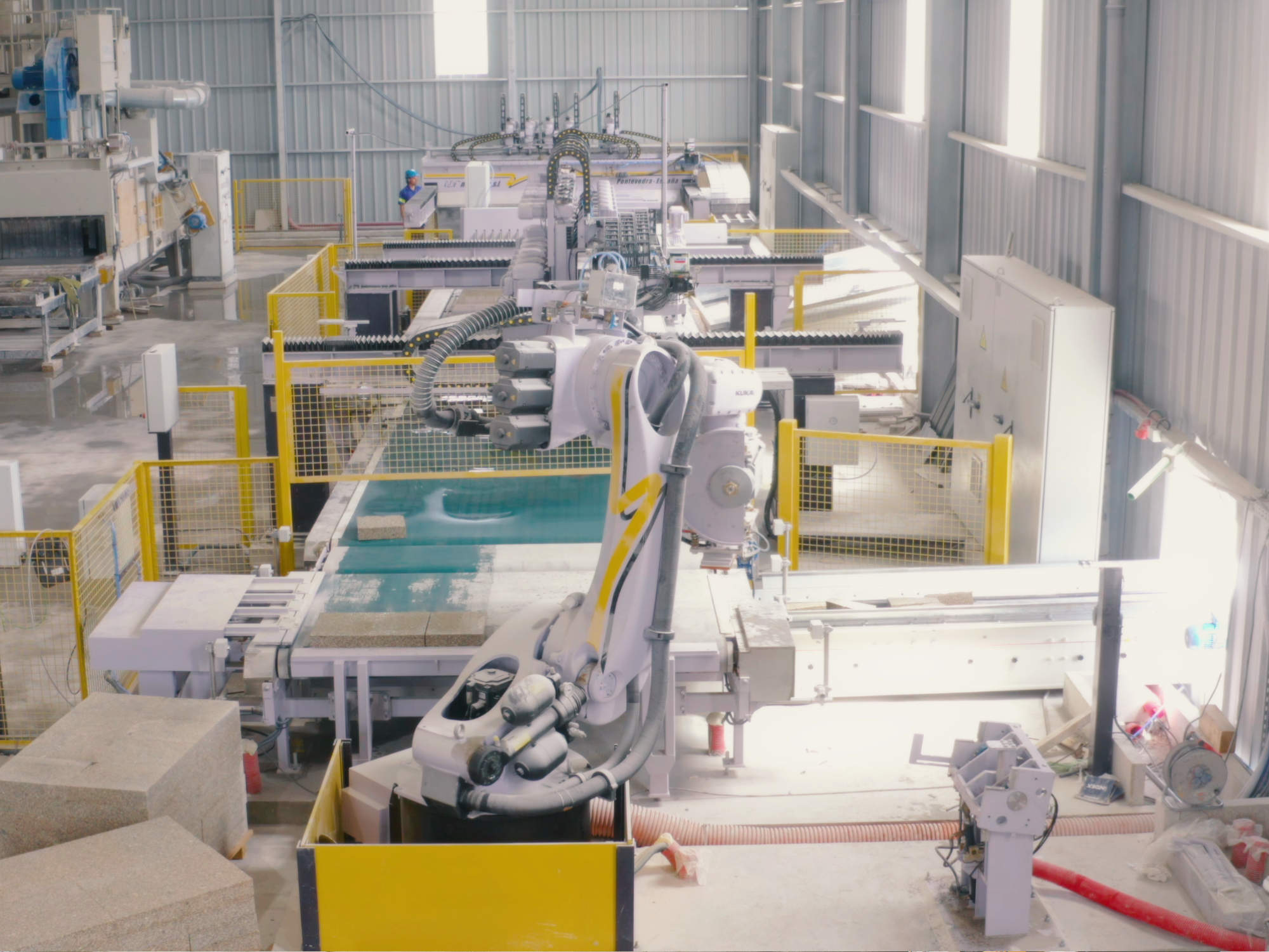
The palletizing robot N-3530 (optional) with its vacuum cup is specially designed to achieve maximum palletizing performance, so this task never interrupts the cutting processes. The proprietary designed suction cup is able to handle horizontal loads up to 120 kilograms.
All dangerous working areas are isolated from personnel access by means if protection fences and optical barriers.
All sensitive parts are linked to a centralized oiling system, reducing the costs of preventive maintenance.
On the electronics side, must be said that all the lines a controlled by last generation automatons, with programs designed in our own departments. Input of data to the cutting line is done via two full colour touch terminals, where all the process parameters can be monitored and easily modified.
| Table width | 2930 mm |
| Maximum table length | 3500 mm |
| Maximum working width | 2200 mm |
| Forwarding speed | 11.5 m/ min |
| Motor power | 1.5 CV |
| Width | 4220 mm |
| Rail track length | 6000 mm |
| Maximum disk distance 1-6 | 2200 mm (inner) |
| Minimum disk distance 1-2-3-4-5-6 | 300 mm |
| Maximum disk diameter | 600 mm |
| Maximum slab thickness/td> | 150 mm |
| Disk motor power | 15 CV (6) |
| Water needs per disk | 15 – 20 l/min |
| Width | 5370 mm |
| Rail track length | 5500 mm |
| Maximum disk distance 1-9 | 3500 mm (inner) |
| Minimum disk distance 1-2-3-4-5-6-7-8-9 | 300 mm |
| Maximum disk diameter | 600 mm |
| Maximum slab thickness/td> | 150 mm |
| Disk motor power | 15 CV (9) |
| Water needs per disk | 15 – 20 l/min |
| Table width | 2960 mm |
| Max. Table length | 4044 mm |
| Max. Band width | 2200 mm |
| Band speed | 11.5 m/ min |
| Band motor power | 3 CV |
| Table width | 2930 mm |
| Maximum table length | 3700 mm |
| Maximum working width | 2200 mm |
| Forwarding speed | 11.5 m/ min |
| Motor power | 1.5 CV |
| Table width | 2930 mm |
| Max. Table length | 3900 mm |
| Max. Working width | 2200 mm |
| Roller speed | 11.5 m/ min |
| Roller motor power | 1.5 CV |
| Centring plate speed | 5 m/ min |
| Transversal motor power | 2.5 CV |
| Table width | 2930 mm |
| Maximum table length | 3500 mm |
| Maximum working width | 2200 mm |
| Forward speed | 11.5 m/ min |
| Band motor power | 3 KW |
| Table dimensions | 1880x3200 mm |
| Frame dimensions | 2560x1140 mm |
| Vacuum pump | 30 m3/h / 1.35 CV |
| Hydraulic power | 5,5 CV |
| Trolley displacement power | 3 CV |
| Table power | 1,5 CV |
| Trolley speed | 5 m/min |
| Slab speed | 11.5 m/ min |
| Maximum input slab width | 2200 mm |


